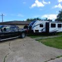
Like most entry level travel trailers, 'Harvey' (our 'Zinger 291RL'), came with only the basic scissor jacks at each corner to stabilize him at the campground.
Levelling was initially accomplished with the use of a truck load of offcut 2" x 6"'s, and later plastic blocks and 'cam like' rockers. A pair of 3 ton bottle jacks with built in ratcheting 'axle' type stands I found work well, but all I found are a bit time consuming and labor intense.
After suffering a few days of lower back discomfort having impinged something while leveling 'Harvey' last time out, I decided to search the internet for a simple, effortless solution that didn't require a $3000 investment, and I think I found it. The 'Ultra-Fab Power Twin II Electric Stabilizer with Dual Motors, 30" and 6000 lbs. of lift looks just the ticket.
https://www.etrailer.com/Camper-Jack...39-941705.html
Harvey tips the DOT scales fully loaded at just under 8000lbs. So to reassure myself this was the route to take, I called the manufacturer for some technical insight, specifically the products weight capacity.
I spoke to Kim in Sales. She knew the product inside out. She answered all my questions, and confirmed that the published 6000lb lift capacity refers to each side, not the combined ability.
Kim assured me that whilst not designed or intended to lift the trailer off it's wheels, it will make light work of making it perfectly level in conjunction with my existing 4500lb tongue jack.
She suggested I speak to Randy in technical support. From his description and knowledge it sounded like he designed and builds each system himself.
After a quick call to the nice people at ‘etrailer’ my order was on it's way.
A few days later the boxes arrived, and deep joy, it's a man-size Erector set.
The kit comprises of four main mechanical pieces for each side. A screw drive in a long channel that comes pre-assembled with the leg already attached, an angled section that bolts on perpendicular to the screw drive and ultimately to the trailer chassis, and two control arms to keep everything aligned that attach to either side of the leg and the aforementioned angled section.

In addition to the mechanicals there are two motors attached to their respective reduction gearboxes and the electrical switches and wiring harness.
The quality and fit of the pieces is impressive, and what surprised me most was the gauge of material used throughout which accounts for it's weight when the two sides are assembled. I took extra time as advised to make sure that the piece of angle that bolts to the trailer chassis and the screwdrive were square to each other to ensure eventual smooth running.
While not in the instructions, I found it necessary to part deploy the legs using the supplied emergency hand crank which fits on a slotted boss where the motors will eventually engage, in order to assemble the two control arms either side of the leg.
The control arms, also formed angle pieces, are connected to the chassis mount and leg using high tensile steel bolts with nyloc-nuts.
Nylon washers are provided to act as bearings where the control arms connect to the leg and chassis mount. One long bolt with a spacer to fit inside the leg connects the control arm on either side of the leg, while the other ends have shorter bolts which completes the triangular configuration.
I was surprised there were no washers provided to fit between the head of the bolts and the nuts on the other side. From vast previous experience this looked like an oversight. And whilst I'm not qualified from an engineering standpoint to discuss the advantages or disadvantages of this omission, for the sake of a dozen steel washers for the six load bearing pivot points, a trip to my local hardware store seemed prudent.
Assembled with a dab of grease the assembly looks and feel right, in my eyes at least.

Once each side was assembled, using the hand crank I checked for full and free movement, SWEET.
After measuring the width of my chassis, I set two saw horses in my garage chassis width apart, 71" in my case. It was then relatively easy to assemble the two halves upside down on the saw horses using the central connecting plate. I now have one fully assembled piece, over 6 feet wide, 3 feet front to back and weighing somewhere north of 80lbs.
I read as much as I could find about installing this hunk of engineered steel under my trailer, and universally, it sounded like a two man job.
You know how men are, we don't ask for directions, don't need instructions, and certainly don't ask for help moving something heavy.
We'd rather spend a day or more in agony with a strained back than admit defeat by an inanimate object. So I got to thinking, why not use it's inherent design to help install the thing?
Using the crank handle, I retracted the legs to their stowed position, this made flipping the assembly over on the garage floor manageable.
I then positioned one end on a movers dolly, (one of those wooden gizmo's with four castoring wheels underneath) this enabled me to 'wheelbarrow' it under Harvey with relative ease. So far so good.
The big feet on the end of the legs make it reasonably stable, and despite being very top heavy, I was able to crank the legs down 6" each side at a time, until the angled chassis mounts made light contact with the underside of Harvey's chassis. At this point there was no danger of the assembly tipping as the length of the chassis mount prevented this, so I got underneath. Using a mallet and wood block to prevent chipping the paint, final positioning of the assembly was a breeze. Once it was near perfect, a turn on the crank each side took some of the weight and effectively locked it in place.
There are six 1/2" diameter holes pre-drilled on each of the chassis mounts. I used high strength 1/4" self-drilling screws with fender washers in each of these straight up into my chassis to give a really solid fit. What sounded like the most difficult step took less than 30 minutes to complete, and I didn't get the slightest twinge from my lower back. Brains over brawn... RESULT!

Once I checked the alignment of the drive pins with the slot cut into the ends of the screw drives, the motors, their molded plastic covers and reduction gearboxes were secured onto the receiver plates with four long bolts. This completed the mechanical part of the installation.
Ultra-Fab supply the two, three position spring loaded switches soldered onto each end of four 15' wires colored White, Green, Red and Black.
Since every installation is different, this makes sense, leaving the end user, to decide where to cut the harness into two. The White wire is for + 12 volt power, green for ground (-12 volt) red for motor drive forward, and black for motor drive reverse.
I decided not to use the switch mounting blocks provided, but instead bought a waterproof project box which would house everything in one neat enclosure.
Inside the box I mounted a buss bar to attach the positive side of my battery. Using crimp ring type connectors each of the white leads from the two switches was attached to my positive buss. The greens (negative) were similarly attached to a ground bolt, one of the self-drilling screws that holds the box to my chassis.
The right side red, with it's inline 30 amp fuse and black leads were cut to about 3 feet in length, ample to reach the right motor just below, and leaving approximately 12' of the Red and Black wires soldered to the other switch to reach the left hand motor on the other side with ease.
In the photo below, the red wire looping around the left side is the main 12 volt feed from the kill switch, it enters the control box at the bottom and connects to the positive buss just visible behind the left inline fuse holder.

The two switches are mounted in either end of the project box with a surplus 0-24 volt LED digital voltmeter I had, recessed into the lid. I want the ability to isolate power to the leg motors to prevent any little fingers that might find the switches from messing with them. A $6.00 battery kill switch from a local auto parts emporium fit the bill perfectly.
To ensure no loss of voltage, I ran a dedicated 6 AWG stranded wire from my tongue mounted battery through cable clips in the channel of my chassis. The power enters the kill switch housing which I control using a removable big red plastic key. In the on position, the digital voltmeter lights up with the available voltage at the buss.
The two control switches, placed logically at each end of the project box, when keyed in the down position lower the legs, and up, raises the legs. They spring back upon release to the neutral position. I can run them simultaneously with no perceivable drop in speed thanks to the 6 gauge feed. Once the feet meet the ground the rpm's drop considerably, but the powerful motors comfortably push the whole trailer up, and dare I say it, will probably lift it off it's wheels.
Despite being tucked up behind the rear wheel, on the outside of the main chassis, and hidden from view by the lower valance, all the controls are easy to reach, especially as I know exactly where they are.

The whole installation took about eight hours over two days. There's quite a lot of drilling involved, most using self-drilling screws.
Planning accounts for about a quarter of the time spent, and well over half of the time was the electrics.
I've found this to be a great addition that anyone who's a bit handy could do in a weekend. The end result is a rock solid travel trailer, leveled with motorized precision on any surface in just minutes, no more backache, no B.S. just awesome.


 Linear Mode